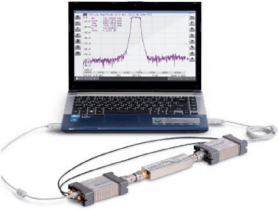
Using a Pair of Copper Mountain Technologies Vector Reflectometers
April 19, 2018Overview
Reflectometers are used to measure the reflection, or S11 parameter, of a Device Under Test (DUT). This measurement only provides characterization of a single-ended device. For analysis of a twoport device, a traditional Vector Network Analyzer (VNA) is typically used. Using Copper Mountain Technologies’ R series reflectometers however, it is possible to configure two of these devices to measure all four S-parameters’ magnitudes for full characterization of a two-port device’s attenuation behavior.
The lowest cost solution that CMT offers for two-port characterization is $9,995 for the S5048, which operates from 20 KHz to 4.8 GHz. Using the specialized R54x2 software package, and two R54 units, two-port characterization can be achieved for as low as $5,990 from 85 MHz to 5.4 GHz. Iterations of this solution then increase in frequency and cost, up to R140x2 from 85 MHz to 14.0 GHz for $10,990.
The R series therefore provides unparalleled ability to reconfigure your measurement setup to your needs. High quality reflectivity measurements as well as S21 and S12 scalar parameters can be recorded at very competitive prices with a variety of frequency range options. S21 and S12 parameters’ phase cannot be measured with this setup however and for measurement of phase characteristics for these two parameters a 2-port VNA is required (the R54x2 setup still measures S11 and S22 phase).
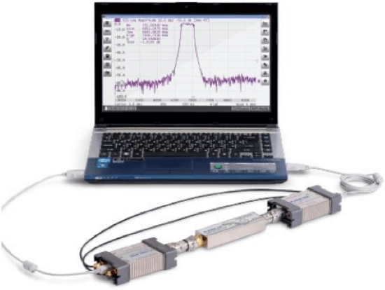
Measurement Setup
The following setup applies only to utilizing two reflectometers simultaneously to take measurements of any S-parameter magnitudes. If the only required measurement is of the S11 parameter, the RVNA suite is the only required software. Any of the RVNAx2 measurement setups (R54x2, R60x2, R140x2) require their own specialized software suite which may be obtained directly from CMT support.
First, install the R54x2 software suite as well as a program called “USB View”. It is necessary for operation of the R54x2.exe that both R54s be plugged into USB ports that share a common USB controller. This is illustrated in a screen capture of USB View in Figure 1. After you have identified two USB ports on your computer that share a controller, starting the R54x2 suite will automatically load both devices.
If this is not the case, unplugging and plugging in the USB cables will revise the issue. It is also not uncommon that a single USB controller on your PC may not have enough power to supply two RVNA units simultaneously. If this is the case one or both units’ LEDs will not light up. This can be remedied by purchasing a powered USB hub, and plugging the units into this device. This error is most common when using two R140s.
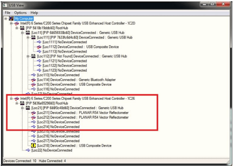
Figure 1: USB View displaying the inputs to the two USB controllers located on the computer this capture was taken on. Notice both PLANAR R54s are connected to the same controller “1C26”.
If a device is not connected between your two R54 (or R60, etc.) units an error message will display in the bottom left corner of the screen reading “Ref. Offset Failure!”. Due to software correction for the drift between the two units’ oscillators, while unconnected by a DUT there is no way for this correction to be made and the error message will display. By looking under the “Devices” softkey on the bottom right side of the R54x2 suite you can set how often this correction takes place.
You should also notice the 2×3 table located there, listing the serial numbers of both connected devices so that you may identify which is listed as port 1 in software. An additional method to determine which unit is listed as Port 1 is to set S11 as your only active trace.
The transmitting unit (taking the measurement of S11) will have its “READY/STANDBY” LED lit green, while the Port 2 unit should be lit red. The transmitting unit will always be lit green for any S-parameter measurement.
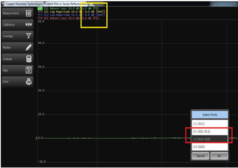
Figure 2: The red box indicates the two selections to make in order to perform a full two-port calibration of the R54 units. The yellow box highlights the appended tags that indicate calibration was performed and corrections are currently on.
Next, SOLT calibration of the reflectometers should be performed to ensure accurate measurement results. DUTs which do not have N-Type connectors (or are an insertable device) require correction for port extensions, and these corrections should be performed prior to SOLT calibration of the instruments. Once you open the calibration menu on the software application you’ll notice there are four calibration options. The middle two options labeled “2-1 (S21 S11)” and “1-2 (S12 S22)” are the only two required for full two-port calibration.
To ensure these operations were performed correctly, both S11 and S22 should have an appended tag in the trace list at the top of the screen reading “[F1]” indicating full one-port calibration. Similarly, S21 and S12 will both have the tag “[Dual]” appended to their spot in the trace list. These tags, along with the calibration sub-menu displaying the two required tests for full two-port calibration are shown in Figure 2. Note that the second parameter listed in each option indicates which port is being SOL calibrated. For the “2-1” measurement, short, open, and load standards should be applied to port 1 in addition to the thru standard connecting both devices.
Measurement Results
Displayed in Figure 3 are the measurement results of a bandpass filter obtained using two R54 devices; as you can see, the measurement acuracy is comparable to that of a two-port VNA. A noise floor of -100 dB is attainable in this frequency range using the “High” power setting, with -80 dB noise floor achievable on the “Low” power setting.
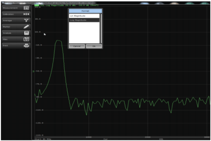
Figure 3: Display of the PlanarR54x2.exe window currently showing S21 measurement of a bandpass filter. The pop-up dialog when selecting the display settings for S21 shows only two options, linear and logarithmic magnitudes
As mentioned previously, the S21 trace being measured in Figure 3 has only two display options, linear magnitude and logarithmic magnitude, due to the fact that the measurement is scalar and not complex. Each channel on the RVNA x2 series instruments can handle four traces at a time, and up to four separate channels may be active in the application. Similar to other CMT VNA series applications, the R54x2 suite of tools allows users to save results in a variety of touchstone formats (.s1p and .s2p, mag. and angle, real and imag.), .csv format, and .png format printed to Word, saved to file, or copied onto the clipboard.
Conclusion
Copper Mountain Technologies RVNA series offers quality vector reflection measurements and together with the capability for measuring scalar transmission S-parameters using a pair of these compact reflectometers. If you have any further questions about the R series 1-port VNAs, or this particular application of the instruments, please feel free to contact CMT support at support@3.141.29.121.


Hi there,
I have a R140 One port reflectometere that I’m using to see the S11 response.
If I’m doing a frequency sweep between 4-6 GHz for 201 points;
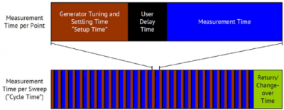
1) Is it possible to have the RVNA software to continuously record the s11 response over time and store per sweep data? 201 points per sweep for one time instance where one time instance is the amount of time it takes to do the sweep from 4-6 GHz?
Thank you so much.