Automated Antenna Testing
April 19, 2018Application Profile
As the number of devices featuring wireless connectivity grows, ensuring their performance specifications while staying within regulatory requirements becomes even more important. Antenna pattern measurement is a critical step in the design process of antennas and wireless devices. Compact antenna measurement systems combined with a high performance VNA are necessary to characterize parameters such as pattern, gain, VSWR, and efficiency. These results are used to validate simulated designs and identify possible performance issues before final testing. By using an in-house measurement system, multiple design revisions can be tested and pre-certified without the high cost of using an accredited or certified measurement facility for each test. Other considerations like portability and low cost are important to engineers in various environments like defense or education, respectively.
Challenges
Making accurate antenna measurements carries a number of challenges, some of the most important being dynamic range, calibration, and speed. A sufficient dynamic range will allow the antenna to be measured accurately at both minimum and maximum signal level with a minimal amount of trace noise. Older network analyzers can reach a reasonable dynamic range and reduced noise by reducing the IF bandwidth, but the analyzer speed is greatly reduced, a single sweep can take many seconds to complete. PC-based VNA’s offer the benefit of greater initial dynamic range, higher speeds, and direct data transfer.
Application: Characterizing the Antenna
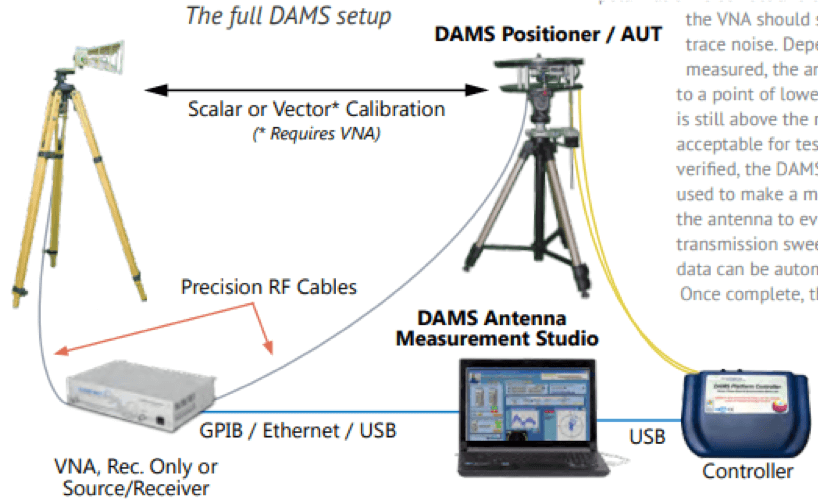
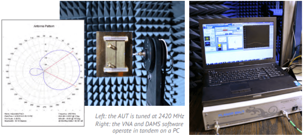
In this example, an unknown 2.4 GHz antenna is characterized, with a configuration consisting of: Diamond Engineering DAMS 5000 positioner with an FSM spherical mount, RF cables, a calibrated reference antenna, a Copper Mountain Technologies Planar 804/1 VNA, and a computer (PC) running the measurement and VNA software. To begin, the VNA is set to the antenna’s frequency range, all RF cable loss (including positioner) is calibrated out using the VNA’s built in 12 term calibration. Once the calibration is complete the AUT is mounted to the positioner’s RF Rotary Joint and the reference antenna is connected then positioned at the appropriate distance (typically 1 or 3 meters). Now that the antennas are connected and the VNA is set to transmission (S12 or S21), the VNA will show the response of the entire link. At this point the user can note the signal response on the analyzer; if the polarization is correct and the AUT is at a point of high signal, the VNA should show a strong profile with little trace noise. Depending on the type of antenna being measured, the antenna can be manually positioned to a point of lowest signal to confirm that the signal is still above the noise floor and the trace noise is acceptable for testing requirements. After the setup is verified, the DAMS automated antenna testing software is used to make a measurement. The software indexes the antenna to every physical point and executes a transmission sweep on the VNA. Optionally, VSWR data can be automatically collected at every point. Once complete, the entire data set can be viewed, processed and exported.
Post-Measurement Analysis and Tuning
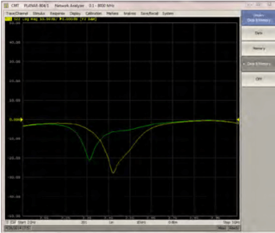
Analyzing the measurement data may reveal certain problems such as low gain, pattern distortion, or frequency response issues. Since the Planar 804/1 VNA is still fully calibrated it can be used to tune and troubleshoot the antenna measurement in real time. For live antenna tuning, the analyzer is switched to S22 mode, and the user can make small modifications to the antenna while seeing the results immediately displayed. To identify multi-path and unwanted environment reflections, the VNA can be switched to S21 Time Domain mode. Reflections outside of the direct path will show up as unusually large spikes indicating that the signal is being reflected. The absorber can now be placed to block the unwanted reflections. After changes have been made to the antenna and/or the test setup, another measurement can be made quickly to verify and record these changes. The end result is a refined antenna design with accurate, publishable test data.
Incorporating a PC-Based VNA
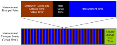
Several specific features and modes of the analyzer were key in this application, including transmission, reflection, VSWR, dynamic range, Time Domain, and sweep speed. All of these are crucial for the measurement and design of antennas and related systems. Antenna measurements contain a large amount of data: a single polarization full spherical measurement using 10-degree resolution and 51 frequencies contains over 33,000 data points. Automated antenna testing using the CMT VNA scripts and DAMS 5000 positioner save many hours compared to manual antenna testing. In this application the VNA’s high measurement speed of 100 µs enabled real-time tuning and fast data collection.


Comments (1)